
Control broadband polarization error
Co-design layer orientation and retardance to reduce wavelength variation over the specified band.
LC WAVEPLATE
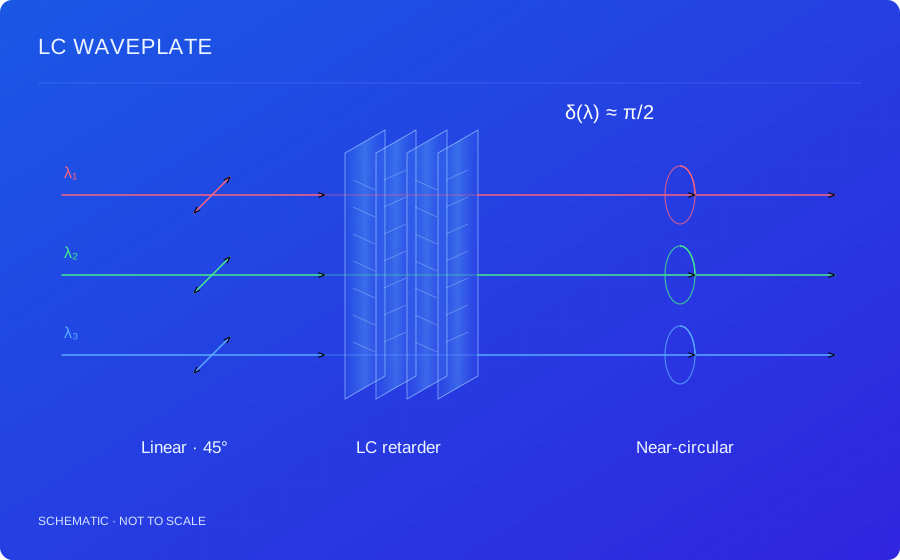
Liquid crystal birefringence and multilayer orientation design control retardance and polarization-conversion error across a specified spectral band.
PRODUCT TERMINOLOGY
Broadband Achromatic Liquid Crystal Waveplate
Related names: Broadband Achromatic LC Waveplate, Achromatic LC Retarder, Liquid Crystal Waveplate
| Name / abbreviation | English expansion | Meaning & scope |
|---|---|---|
| LC waveplate | Liquid Crystal Waveplate | A broadband achromatic version additionally requires a defined spectral range and allowable polarization error. |
| Retarder | Polarization Retarder / Retardation Plate | An element introducing relative phase delay between polarization components; closely related to the term waveplate. |
| QWP | Quarter-Wave Plate | A waveplate targeting approximately π/2 retardance under the design conditions. |
| HWP | Half-Wave Plate | A waveplate targeting approximately π retardance; its function differs from that of a QWP. |
QWP and HWP describe target retardance. Broadband and achromatic describe spectral requirements; both should be specified.
01 / HOW IT WORKS
A waveplate controls output polarization through the phase difference accumulated by two eigenpolarizations. In an ideal uniform-axis layer, retardance depends on effective birefringence, thickness and wavelength. Quarter-wave retardance can produce near-circular output for an appropriate linear input orientation; half-wave retardance supports linear-polarization rotation or circular-handedness conversion.
δ(λ) = 2πΔneff(λ)d / λ
δ is retardance and d is thickness. Effective birefringence depends on dispersion, incident angle and optical-axis orientation.
Single-layer retardance generally varies with wavelength. A broadband design controls the equivalent polarization response over a specified interval. Layers with different orientations, thicknesses or twist profiles may be optimized with Jones matrices or a fuller anisotropic model. The required layer count and composition follow the target rather than a universal fixed recipe.
Specify fast-axis orientation, conversion efficiency, ellipticity or extinction ratio as appropriate, in addition to equivalent retardance. Broadband requirements include the full interval and allowable error, together with angular range, temperature, clear aperture and spatial uniformity. A center-wavelength value alone is insufficient.
When combining waveplates with polarizers, reflective films, lenses or gratings, track polarization through the entire optical path. Substrates, adhesives and stress can introduce additional retardance. Output polarization and loss must be checked in the integrated stack under agreed conditions.
Background: LC polarization holography, geometric phase and volume diffraction ↗
02 / TECHNICAL BENEFITS
Co-design layer orientation and retardance to reduce wavelength variation over the specified band.
Liquid crystal polymer layers can integrate with substrates or other films for compact conversion and compensation.
Design quarter-wave, half-wave or other equivalent transformations together with axis, aperture uniformity and angle constraints.
03 / DESIGN INPUTS
These are the inputs for a design assessment, not fixed product specifications. Numerical performance, test conditions and delivery scope are confirmed for the agreed design.
| Parameter | Requirements to discuss |
|---|---|
| Spectral range | Specify the full operating wavelength interval. |
| Retardance / tolerance | Define half-wave, quarter-wave or other target retardance. |
| Aperture / uniformity | Specify the usable area and spatial tolerance. |
| Incidence / substrate | Evaluate angular conditions, substrate and mounting. |
04 / APPLICATIONS
01
Rotate linear polarization or convert between linear and circular states within the operating interval.
Design conditionsSpecify retardance, allowable error, input orientation and spectral band together.
02
Combine with reflective polarizers, polarizers and lenses to assess broadband evolution and compensation.
Design conditionsInclude adhesives, substrates and oblique-incidence retardance in the complete stack.
03
Provide custom retarders for multiwavelength measurement, imaging and polarization-sensitive optics.
Design conditionsMatch calibration procedures, temperature and angular conditions for precision measurements.
Suitability depends on the complete optical system and must be assessed against your operating conditions.
05 / COMMON QUESTIONS
No. Provide the operating interval and the allowed retardance error over that interval. Incidence angle and temperature conditions should also be defined where relevant.
Send the target retardance and operating conditions. The design and feasibility will be evaluated for the requested optical function.
TECHNICAL REQUIREMENTS
Share the target optical function, spectrum, aperture, polarization and system-integration conditions.