PRODUCT TERMINOLOGY
Names & abbreviations
Liquid Crystal Electrically Tunable Lens & Geometric Phase Lens
Related names: LC-ETL, Liquid Crystal Tunable Lens, PB Lens, Geometric Phase Lens
Product names, expansions and terminology scope| Name / abbreviation | English expansion | Meaning & scope |
|---|
| LC-ETL | Liquid Crystal Electrically Tunable Lens | This page covers a focal-switching architecture combining a PB lens and an electrical polarization switch. |
|---|
| ETL | Electrically Tunable Lens | A broader term that also includes technologies such as variable liquid interfaces; it does not identify the operating mechanism by itself. |
|---|
| LC lens | Liquid Crystal Lens | A general term covering different materials, structures and tuning mechanisms, rather than this complete assembly alone. |
|---|
| PBL / GPL | Pancharatnam–Berry Lens / Geometric Phase Lens | The phase-lens component in this architecture. Electrical focal-state switching additionally requires polarization control. |
|---|
Focal-state selection and system optical power must be distinguished from continuous optical zoom. The PB lens can also be assessed as a passive phase element.
01 / HOW IT WORKS
Device principles & design approach
PB geometric phase and the lens wavefront
A liquid crystal PB lens encodes phase through a spatial optical-axis azimuth α(x,y). Near the design wavelength and half-wave retardance, incident circular polarization mainly converts to the opposite handedness and acquires geometric phase set by that azimuth. A radial phase profile produces a converging or diverging transmitted wavefront.
φσ(x,y) = 2σ α(x,y); φlens(r) ≈ −πr² / (λ₀f₀)
σ = ±1 denotes the two circular states under the chosen convention. The lens expression is a paraxial approximation at design wavelength λ₀ and focal length f₀, with a constant phase omitted.
Electrical focal-state selection
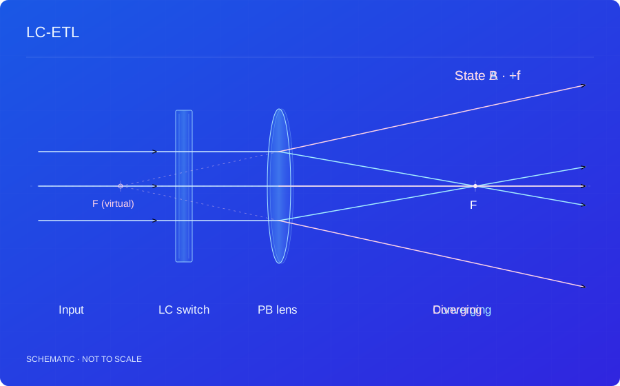
A polarization switch before the PB lens changes incident circular polarization and selects conjugate geometric-phase profiles. For an ideal single PB lens, these correspond to opposite signs of optical power. Multiple focal states may be assessed using cascaded lenses and polarization switches together with the system transfer characteristics.
Focal states and system optical power
Switching one element between ±f differs from continuous optical zoom of a complete imaging system. Effective focal length, virtual-image distance and focal-plane position also depend on spacing and other optics. VR varifocal designs require joint consideration of the eye box, field of view, display optics and target virtual-image distance.
Efficiency, response and image quality
Polarization conversion depends on retardance, wavelength, angle and polarization purity. Switching response must be measured with the polarization switch, drive waveform and operating temperature. Image-quality assessment also includes wavefront error, chromatic error, zero-order leakage, aperture and consistency between focal states.
Principle references+
Background: LC polarization holography, geometric phase and volume diffraction ↗
02 / TECHNICAL BENEFITS
Characteristics & benefits
01Large aperture and high optical power
PB geometric-phase patterns form the lens wavefront within a thin LC layer, supporting designs with large apertures and high dioptric power. Aperture and optical power can be co-designed with orientation-pattern resolution, wavefront error and system aberrations.
Fast electrical focal-state switching
An electrical polarization switch selects the PB lens focal state without translating and settling a lens group, enabling synchronization with display, imaging and measurement timing. Actual switching speed depends on the polarization switch, drive waveform and operating temperature.
Thin, lightweight optical structure
Focusing is encoded in the LC orientation structure. Film-based PB lenses, polarization switches and substrates can form a planar optical stack that reduces axial thickness and mechanical travel space for modules constrained by size and weight.
Low-power electrical drive
The PB phase layer provides focusing, while electrical control mainly changes polarization without a motor driving a lens group. Low-power polarization switches and operating sequences can optimize drive power; system energy use is assessed with the complete drive circuit and operating mode.
Solid-state, silent focusing
LC orientation and polarization switching control focal states without macroscopic lens motion or mechanical actuators. This avoids mechanical noise from focusing motors and transmissions, supporting solid-state, silent varifocal and focusing modules.
Multiple focal states and programmable control
Cascaded lenses and polarization switches combine different optical-power states for focal-plane selection and electronic timing control. State range, state count and system effective focal length are co-designed; focal-state switching and continuous optical zoom of a complete imaging system must be defined separately.
03 / DESIGN INPUTS
Design variables & assessment conditions
These are the inputs for a design assessment, not fixed product specifications. Numerical performance, test conditions and delivery scope are confirmed for the agreed design.
Custom design requirements| Parameter | Requirements to discuss |
|---|
| Focal states / optical power | Define target states and optical layout for evaluation. |
|---|
| Operating spectrum / aperture | Specify the wavelength range and usable aperture. |
|---|
| Switching / drive requirements | Response and drive conditions are evaluated for the design. |
|---|
| Input polarization / integration | Confirm polarization states, stack and mechanical envelope. |
|---|
04 / APPLICATIONS
Applications & system integration
01
VR varifocal and multifocal displays
Select virtual-image distance or focal plane according to display depth when investigating accommodation cues and image depth.
Design conditionsCo-design timing, eye box, field of view and imaging optics; a single ±f value does not characterize system focusing.
02
Multistate imaging and measurement
Select focal planes, sample depth or change measurement focus in a path with known polarization.
Design conditionsDefine state count, image quality, spectral range and switching response.
03
Compact programmable optics
Replace selected mechanical focal adjustments with electronic state control in laboratory systems and prototypes.
Design conditionsAssess discrete-state suitability; continuous zoom requires separate architecture evaluation.
Suitability depends on the complete optical system and must be assessed against your operating conditions.
05 / COMMON QUESTIONS
Device characteristics & selection
Is an LC-ETL the same as a liquid lens?+
This design uses a liquid crystal PB lens and polarization switching, rather than changing the shape of a liquid interface. Its focal-state behavior must be assessed for the intended system.
What is needed to start a custom design?+
Send the spectrum, aperture, required focal states, switching requirements and input polarization. An optical layout helps us assess integration.