
Reflective deflection and focusing
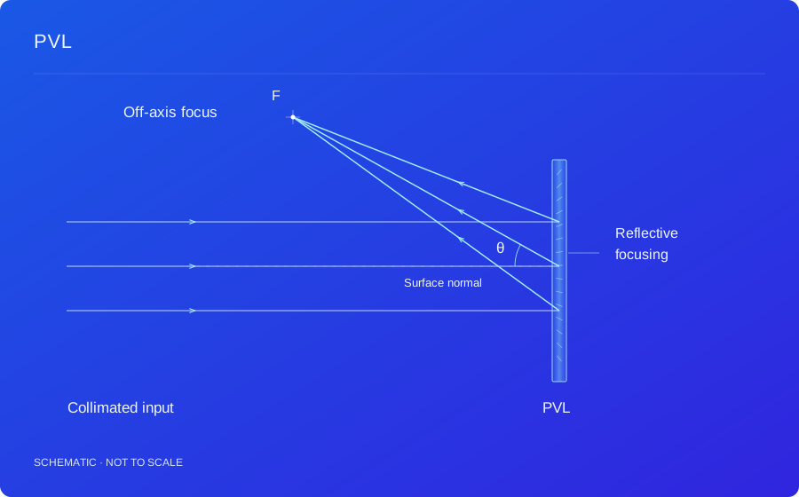
One volume element forms an off-axis converging wavefront, providing an option for systems requiring both folding and optical power.
PVL
A spatially varying liquid crystal polarization volume structure combines reflective deflection and off-axis focusing in one element.
PRODUCT TERMINOLOGY
Off-Axis Reflective Polarization Volume Lens
Related names: PVL, Reflective Polarization Volume Lens, Off-Axis Reflective Lens
| Name / abbreviation | English expansion | Meaning & scope |
|---|---|---|
| PVL | Polarization Volume Lens | This page describes a liquid crystal off-axis reflective PVL combining reflective deflection with focusing. |
| Reflective PVL | Reflective Polarization Volume Lens | Specifies reflective operation. Off-axis identifies a focus or chief ray displaced from the selected axis. |
| Off-axis reflective lens | Off-Axis Reflective Lens | A broader functional and geometric label. Here it specifically refers to a liquid crystal polarization volume structure. |
| OAP — different device | Off-Axis Parabolic Mirror | A shaped reflective surface that focuses light; it is structurally different from a PVL operating by volume diffraction. |
The distinction between PVL and PVG is the target wavefront: this PVL provides off-axis reflective focusing, while the PVG page focuses on coupling and specified diffraction directions.
01 / HOW IT WORKS
A PVL encodes the target lens wavefront in three-dimensional liquid crystal orientation and the local volume-grating distribution. Unlike a grating targeting a single deflection direction, different aperture positions direct the selected reflected polarization channel toward a common focus.
An off-axis target focus or chief ray departs from the selected axis, allowing input and reflected output paths to separate. Object and image positions, incident wavefront and mounting coordinates jointly define the design. One off-axis angle alone does not specify the full focusing or imaging requirement.
A reflective LC PVL uses the anisotropic volume response to control the wavefront of a selected polarization channel. Local grating orientation and period must match the propagation geometry. Changes in wavelength, angle or polarization can affect efficiency and focal quality.
kd(r) = ki(r) + K(r)
r identifies position on the device and K(r) is the local grating vector. The equation expresses local phase matching; efficiency and wavefront require electromagnetic and propagation analysis.
Assess spectrum, polarization, aperture, object and image positions, off-axis geometry and packaging together. Validation can combine polarization-resolved spectral–angular scans, efficiency, wavefront and focal-spot measurements. Imaging applications also require off-axis aberration, field-of-view and complete-system image-quality checks.
Background: LC polarization holography, geometric phase and volume diffraction ↗
02 / TECHNICAL BENEFITS
One volume element forms an off-axis converging wavefront, providing an option for systems requiring both folding and optical power.
LC orientation and the volume-grating distribution carry the optical function; total thickness also includes substrate and packaging.
The target polarization channel can be co-designed with other polarizing optics, with selectivity and efficiency verified under use conditions.
03 / DESIGN INPUTS
These are the inputs for a design assessment, not fixed product specifications. Numerical performance, test conditions and delivery scope are confirmed for the agreed design.
| Parameter | Requirements to discuss |
|---|---|
| Wavelength / polarization | Define the operating spectrum, handedness convention and angular range. |
| Focal geometry / off-axis angle | Specify incident wavefront, object and image positions and the chief-ray direction. |
| Aperture / wavefront requirements | Set aperture, wavefront or spot-quality targets and tolerances. |
| Efficiency / integration | Evaluate efficiency under specified spectral and angular conditions with the substrate and stack. |
04 / APPLICATIONS
01
Combine reflective deflection with a specified focus while separating input and output paths.
Design conditionsProvide object/image geometry, field, aperture and wavefront or image-quality requirements.
02
Assess combining collimation, focusing or coupling in a polarization volume element.
Design conditionsCo-design substrate index, total-internal-reflection conditions, target directions and spectrum.
03
Develop compact paths, focusing experiments and custom holographic wavefront modules with known polarization.
Design conditionsSpecify handedness conventions, angular distributions, parasitic channels and measurement conditions.
Suitability depends on the complete optical system and must be assessed against your operating conditions.
05 / COMMON QUESTIONS
Both are polarization volume holographic elements. A PVL shapes a focusing wavefront, while a grating is typically designed for coupling into a specified diffraction direction.
No. A PVL uses an anisotropic volume-diffraction structure; an OAP uses a shaped reflective surface. Their polarization and spectral behavior differ.
Neither function should be assumed from the PVL name. Additional switching or achromatic requirements need separate architecture and system assessment.
TECHNICAL REQUIREMENTS
Share the target optical function, spectrum, aperture, polarization and system-integration conditions.