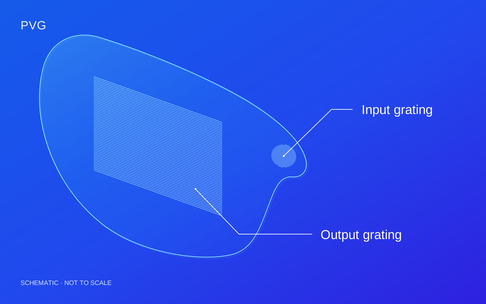
PVG waveguide coupling regions: Input grating and Output grating. Grating periods, regions and substrate geometry are schematic rather than product dimensions.
PRODUCT TERMINOLOGY
Names & abbreviations
Liquid Crystal Polarization Volume Grating
Related names: PVG, Polarization Volume Grating, Polarization Volume Holographic Grating
Product names, expansions and terminology scope
Name / abbreviation
English expansion
Meaning & scope
PVG
Polarization Volume Grating
The liquid crystal volume grating described here is designed for polarization-selective volume diffraction.
Volume holographic grating
Polarization Volume Holographic Grating
A fuller name emphasizing the volume-holographic structure; it refers to the same product family in this context.
PVH
Polarization Volume Hologram
A broader class that can include gratings, lenses and other wavefront functions, rather than PVG alone.
PVG and PVL are polarization volume elements with different target wavefronts. Specify coupling or focusing requirements when selecting an element.
01 / HOW IT WORKS
Device principles & design approach
Three-dimensional orientation and volume diffraction
A polarization volume grating encodes an anisotropic dielectric structure through periodic liquid crystal orientation in the plane and through the thickness. The reflective PVG discussed here uses a cholesteric liquid crystal polymer. Its helix, in-plane period and slant jointly determine diffraction geometry and polarization selectivity; a scalar surface-relief model alone does not describe this structure.
Bragg matching and polarization selection
Incident and diffracted waves couple under the volume grating phase-matching condition. Period and orientation determine the grating vector. Wavelength, angle and polarization changes affect efficiency and output direction, so spectral and angular response, polarization conversion and parasitic orders must be evaluated together.
kd = ki + K
k_i and k_d are wave vectors inside the device medium; K is the relevant grating vector. This specifies phase matching. Efficiency requires an anisotropic coupled-wave or electromagnetic model.
Waveguide input and output coupling
For AR waveguides, an input grating couples external light into a direction that satisfies total internal reflection in the substrate; an output grating couples guided light toward the viewing region. Substrate index, propagation angles, coupling regions, pupil geometry and energy distribution across fields and wavelengths must be co-designed. Grating efficiency is different from total display-system efficiency.
Thickness, slant and color-efficiency design
LC-layer thickness, grating slant, period and birefringence jointly influence volume diffraction and polarization conversion. Single- or multilayer optimization can tailor coupling efficiency across RGB wavelengths and fields to control color balance and brightness. Output regions also require spatial coupling-strength design for pupil energy distribution. Validation includes spectral–angular scans, polarization-resolved measurements, leakage and spatial uniformity.
Reflective PVGs use polarization-selective volume diffraction to direct light in the designed channel toward the intended propagation direction, helping reduce unwanted forward leakage. Co-designing LC layer thickness, polarization evolution and waveguide propagation geometry can further suppress leakage and stray light caused by repeated coupling.
02
High efficiency and effective optical-energy use
Under matched wavelength, angle and polarization conditions, PVGs can achieve high diffraction efficiency and concentrate energy in the intended diffraction channel. Co-designing input and output gratings with the propagation path can improve useful optical-energy utilization; individual grating efficiency and the complete waveguide efficiency to the eye must be assessed separately.
03
Color and diffraction-efficiency design freedom
LC layer thickness, grating slant, period and multilayer structures provide joint design variables for coupling efficiency across RGB bands and fields of view. Together with spatial efficiency profiles across the output region, these variables can optimize color balance, brightness uniformity and energy distribution within the eye box.
04
Low-cost mass production
Photoalignment, LC film fabrication and curing form the grating structure with less reliance on complex micro- and nanoscale etching, supporting large-area batch fabrication and lower unit costs at production scale. Actual cost depends on the process, layer count, yield and production volume.
05
Thin-film structure and waveguide integration
Orientation within the LC polymer carries the optical function, allowing custom coupling regions on planar substrates with reduced coupling-element thickness. The film and waveguide substrate can be co-designed for integration in thin, lightweight optical modules.
03 / DESIGN INPUTS
Design variables & assessment conditions
These are the inputs for a design assessment, not fixed product specifications. Numerical performance, test conditions and delivery scope are confirmed for the agreed design.
Custom design requirements
Parameter
Requirements to discuss
Spectrum / angular response
Define wavelengths, incidence angles and diffraction targets.
Coupling geometry
Assess in-coupling / out-coupling with the waveguide design.
Efficiency / uniformity
Define measurement conditions and spatial requirements.
Substrate / usable area
Evaluate substrate, grating area and integration method.
04 / APPLICATIONS
Applications & system integration
01
AR waveguide input coupling
Connect external display optics to the guided path by coupling light into the required substrate propagation direction.
Couple guided light toward the viewing region and design the spatial energy distribution across the output pupil.
Design conditionsAssess field of view, eye box, uniformity, utilization and repeated coupling.
03
Polarization-selective volume optics
Develop and validate coupling elements for specified wavelength, angle and polarization channels.
Design conditionsBroadband or broad-angle operation requires joint design and validation.
Suitability depends on the complete optical system and must be assessed against your operating conditions.
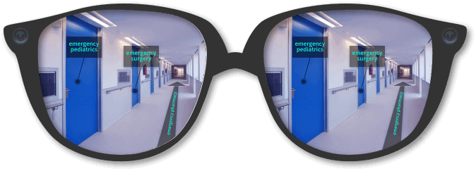
AR optical application illustration from our existing product materials.
05 / COMMON QUESTIONS
Device characteristics & selection
Are LCPG and PVG interchangeable?+
They use different grating architectures and have different spectral and angular behavior. Selection depends on the optical function and system constraints.
Do you provide complete AR displays?+
This page describes optical grating and coupling-element development. Contact us to define the required component and the scope of waveguide integration.