
Electrical optical-power control
Director and optical-path control adjust focus with less reliance on axial mechanical translation, supporting synchronized imaging and measurement.
GRIN LC LENS
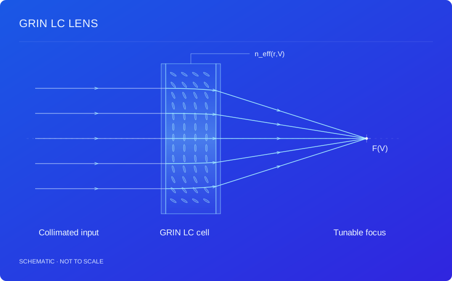
Electrical control of liquid crystal orientation and the effective-index profile creates a tunable lens phase within a planar LC cell.
PRODUCT TERMINOLOGY
Gradient-Index Liquid Crystal Lens
Related names: GRIN LC Lens, Gradient-Index Liquid Crystal Lens, Graded-Index LC Lens, Electrically Tunable GRIN LC Lens
| Name / abbreviation | English expansion | Meaning & scope |
|---|---|---|
| GRIN | Gradient Index / Graded Index | A spatially varying refractive index, not limited to liquid crystal materials. |
| GRIN LC lens | Gradient-Index Liquid Crystal Lens | A lens using the spatial effective-index profile of liquid crystal to create optical-path differences. LC means Liquid Crystal. |
| Tunable GRIN LC lens | Electrically Tunable GRIN LC Lens | Drive-dependent director and effective-index profiles tune optical power. Material, polarization and drive conditions must be stated. |
| LC-ETL — broader term | Liquid Crystal Electrically Tunable Lens | A broader tunable-lens label. The LC-ETL page here focuses on PB phase and polarization switching; this page focuses on GRIN optical-path control. |
GRIN modulation uses effective-index optical-path differences. Geometric-phase modulation uses optical-axis orientation and polarization conversion; the mechanisms should be distinguished.
01 / HOW IT WORKS
GRIN describes a spatially varying refractive index. In an LC lens, director orientation sets the effective index for a given propagation direction and polarization. Different optical paths across a planar cell create the phase curvature required for lens action.
Δφ(r,V) = (2π/λ) ∫[neff(r,z,V) − nref(z,V)] dz
r denotes aperture position, z is the thickness coordinate and V represents drive conditions. This is a scalar optical-path approximation for the applicable polarization channel; complex orientation or large angles require an anisotropic model.
Electrode geometry, voltage distribution and boundary alignment jointly determine the director field. A nonuniform field changes director tilt, the effective-index profile and optical power. Fringe-field, multi-electrode and resistive-layer architectures have different operating constraints and should be chosen for the target aperture and wavefront.
Within a calibrated drive interval, electrical signals may select continuous or specified optical-power states. Common single-layer nematic designs depend on the input linear-polarization direction. Unpolarized operation, positive/negative power switching or specialized phase profiles require further material, stack and drive assessment.
Available optical-path difference is constrained by birefringence and cell thickness. Larger apertures or higher optical power require more center-to-edge phase difference. Cell thickness also affects director relaxation and response, so power range, aperture, timing, wavefront error, dispersion, temperature and long-term stability must be assessed together.
Background: LC anisotropy and director control ↗
02 / TECHNICAL BENEFITS
Director and optical-path control adjust focus with less reliance on axial mechanical translation, supporting synchronized imaging and measurement.
An internal index gradient provides lens action within a cell designed with planar substrates, transparent electrodes and peripheral electronics.
Co-design electrodes and drive mappings for target optical power, defocus compensation and focal-plane selection.
03 / DESIGN INPUTS
These are the inputs for a design assessment, not fixed product specifications. Numerical performance, test conditions and delivery scope are confirmed for the agreed design.
| Parameter | Requirements to discuss |
|---|---|
| Optical power / aperture | Specify the focal range, aperture and working distance. |
| Spectrum / polarization | Define the spectrum, angular range and input polarization. |
| Drive / response | Evaluate electrode architecture, AC drive and settling requirements. |
| Wavefront / integration | Set image-quality targets, substrates and integration constraints. |
04 / APPLICATIONS
01
Adjust the focal plane in cameras or microscopes with defined polarization and optical-path conditions.
Design conditionsConfirm object distance, aperture, image quality, spectrum and settling time together.
02
Electrically compensate known defocus or change focus between measurement planes.
Design conditionsProvide focal range, wavefront error, repeatability and calibration requirements.
03
Develop experimental elements or systems around an index gradient and drive-dependent phase profile.
Design conditionsDefine acceptable polarization dependence, temperature range, drive space and optical tolerances.
Suitability depends on the complete optical system and must be assessed against your operating conditions.
05 / COMMON QUESTIONS
A GRIN lens uses an effective-index profile to generate optical path differences. A geometric phase lens encodes phase in the spatial optical-axis azimuth and its polarization conversion.
A single nematic LC layer is generally polarization dependent. Polarization-independent use requires an appropriate architecture and validation.
Continuous electrical control may be designed within a validated operating range. Usable range and image quality depend on the complete device and drive architecture.
TECHNICAL REQUIREMENTS
Share the target optical function, spectrum, aperture, polarization and system-integration conditions.