PRODUCT TERMINOLOGY
Names & abbreviations
Liquid Crystal Beam Steering & Polarization Grating
Related names: LCPG, Liquid Crystal Polarization Grating, PB Phase Grating, LC Beam Steerer
Product names, expansions and terminology scope| Name / abbreviation | English expansion | Meaning & scope |
|---|
| LCPG | Liquid Crystal Polarization Grating | This page focuses on a thin PB phase-steering approach using in-plane orientation variation. |
|---|
| PG | Polarization Grating | A general abbreviation whose structural scope can vary across publications. Check the material and diffraction mechanism. |
|---|
| PB grating | Pancharatnam–Berry Phase Grating | A name emphasizing geometric-phase operation in the thin polarization-grating context discussed here. |
|---|
| Beam steerer | Liquid Crystal Beam Steerer | The complete steering device or assembly. Distinguish a passive grating from an electrical assembly that includes a polarization switch. |
|---|
LC means Liquid Crystal; PB means Pancharatnam–Berry. Similar names do not imply identical angles, spectra or drive requirements.
01 / HOW IT WORKS
Device principles & design approach
Periodic orientation and phase gradients
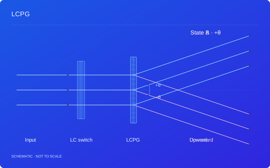
An LCPG creates a phase gradient through periodic in-plane optical-axis rotation. At the design half-wave condition, opposite circular input states acquire opposite phase slopes and generate principal diffraction components in opposite directions. Here Λ is the repeat period of the equivalent director orientation and corresponds to a 2π phase change.
α(x) = πx / Λ; φσ(x) = 2σ α(x) = 2πσx / Λ
α is the optical-axis azimuth and σ = ±1 labels the chosen polarization convention. The orientation gradient sets the steering plane.
Diffraction direction and electrical switching
The grating produces polarization-dependent diffraction. An electrical beam steerer combines that grating with a polarization switch. Switching incident circular polarization selects opposite diffraction orders. Upward and downward in the drawing refer to the chosen coordinate plane; physical directions depend on mounting and grating-vector orientation.
sinθd − sinθi = mλ / Λ
This grating equation assumes both incident and output propagation in air, with angles measured from the normal. The principal components commonly correspond to m = ±1; other media require their refractive indices.
Conversion efficiency and leakage
For an ideal thin PB grating, local retardance determines polarization conversion. Departures from the half-wave condition increase unconverted light and zero-order leakage. Practical design also includes dispersion, orientation error, interface losses, incident angle and aperture uniformity.
ηconv ≈ sin²(δ/2); δ = 2πΔneff d / λ
This ideal uniform-retardance relation excludes absorption, reflection and fabrication-defect losses.
Cascaded steering and control
Multiple steering states can be formed by cascading gratings and polarization switches. Periods, mounting azimuths, polarization states and spacings jointly determine the output direction and clear optical path. Angular accumulation, interstage polarization matching, crosstalk and total efficiency must be checked. Response is assessed for the complete driven assembly.
Principle references+
Background: LC polarization holography, geometric phase and volume diffraction ↗
02 / TECHNICAL BENEFITS
Characteristics & benefits
01Large aperture and wide-angle beam steering
Planar LC orientation patterns support beam-deflection designs with large apertures; grating period and mounting azimuth determine the steering direction and angle. Multiple grating and polarization-switch stages can extend the steering range and available angle states while co-optimizing clear aperture, angular dispersion and efficiency.
Fast electrical direction switching
A polarization switch selects the diffraction channel for fast electronic changes in beam direction, without waiting for a mechanical steering assembly to move and settle. Switching response depends on the polarization switch, drive and temperature, and can be designed around scanning or channel-selection timing.
Thin, lightweight planar optics
Periodic orientation within an LC film provides beam deflection. The grating, polarization switches and other films can form a compact optical stack that reduces the size, weight and movement space of a steering assembly, supporting thin modules and multistage integration.
Low-power electrical drive
The grating provides phase-based deflection, while electrical drive mainly switches polarization without a motor moving mirrors or lenses. Low-power operation can be designed through polarization-switch selection and addressing sequences, with total power assessed across all stages and control circuits.
Solid-state, silent beam steering
LC orientation and polarization control the output direction without macroscopic moving mirrors, rotation stages or mechanical actuators. This reduces mechanical wear and motion-related noise, supporting solid-state, silent beam-control and optical-routing modules.
High efficiency and multistage angular addressing
Near the design half-wave condition and with matched input polarization, optical energy can be directed efficiently into the intended diffraction channel. Cascading gratings with different periods and azimuths provides angular addressing while co-optimizing zero-order leakage, polarization matching between stages and total transmission efficiency.
03 / DESIGN INPUTS
Design variables & assessment conditions
These are the inputs for a design assessment, not fixed product specifications. Numerical performance, test conditions and delivery scope are confirmed for the agreed design.
Custom design requirements| Parameter | Requirements to discuss |
|---|
| Diffraction / steering angle | Evaluate the angle together with wavelength and grating period. |
|---|
| Wavelength / polarization | Specify the incident spectrum and polarization state. |
|---|
| Efficiency / usable aperture | Define target performance and measurement conditions. |
|---|
| Switching architecture | Assess polarization switches, cascades and integration. |
|---|
04 / APPLICATIONS
Applications & system integration
01
Beam steering and discrete angular scanning
Switch electronically between directions or combine stages for discrete angular addressing.
Design conditionsSpecify angle states, polarization, aperture, crosstalk and total cascade efficiency.
02
Polarization-controlled optical routing
Map polarization states to output directions for path selection, splitting and channel management.
Design conditionsAssess spectrum, polarization purity, zero-order leakage and downstream collection.
03
Compact diffractive prototypes
Evaluate diffraction layouts in space-constrained systems seeking fewer moving components.
Design conditionsSet direction jointly with wavelength and period; assess angular dispersion for broadband input.
Suitability depends on the complete optical system and must be assessed against your operating conditions.
05 / COMMON QUESTIONS
Device characteristics & selection
Is the grating itself electrically switched?+
The architecture shown combines a polarization grating with an electrically controlled polarization switch. Describe whether you need a passive grating or a complete beam-steering assembly.
Can the deflection angle be customized?+
Angle requirements can be evaluated with the wavelength, aperture, polarization and intended optical layout. Feasibility is confirmed through design assessment.